
Kinh Doanh 1: 07.6464.9556 ( Zalo )
Kinh Doanh 2: 0909 752 144
SHIP CODE TOÀN QUỐC*
Kỹ thuật 1: 07 6464 9556 ( Zalo )
Kỹ thuật 2 : 0977 812 351
https://www.tiktok.com/@vinitechdn
Danh mục sản phẩm
Sản phẩm hot


Tin tức

Liên kết website
Thống kê
- Đang online 0
- Hôm nay 0
- Hôm qua 0
- Trong tuần 0
- Trong tháng 0
- Tổng cộng 0
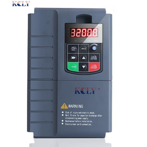
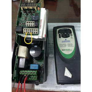
Lỗi biến tần INVT
VINITECH chuyên sửa chữa biến tần, servo tại Đồng Nai, Bình Dương...
|
|||||||||||||||||||||||||||||||||||||||||||||||||
|
|
||||||||||||||||||||||||||||||||||||||||||||||||||||||||||||||||||||||||||||||||||||||||||||||||||||||||||||||
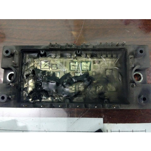
Lỗi biến tần INVT :gd20,chf100
Fault and Trouble shooting
| Fault Code |
Fault Type | Reason | Solution |
| OUT1 | IGBT Ph-U fault |
1. Acc/Dec time is too short. 2. IGBT module fault. 3. Malfunction caused by interference. 4. Grounding is not properly. |
1. Increase Acc/Dec time. 2. Ask for support. 3. Inspect external equipment and eliminate interference. |
| OUT2 | IGBT Ph-V fault | ||
| OUT3 | IGBT Ph-W fault |
||
| OC1 | Over-current when acceleration |
1. Short-circuit or ground fault occurred at inverter output. 2. Load is too heavy or Acc/Dec time is too short. 3. V/F curve is not suitable. 4. Sudden change of load. |
1. Inspect whether motor damaged, insulation worn or cable damaged. 2. Increase Acc/Dec time or select bigger capacity inverter. 3. Check and adjust V/F curve. 4. Check the load. |
| OC2 | Over-current when deceleration |
||
| OC3 | Over-current when constant speed running |
||
| OV1 | Over-voltage when acceleration |
1. Dec time is too short and regenerative energy from the motor is too large. 2. Input voltage is too high. |
1. Increase Dec time or connect braking resistor 2. Decrease input voltage within specification. |
| OV2 | Over-voltage when deceleration |
||
| OV3 | Over-voltage when constant speed running |
||
| UV | DC bus Under-voltage |
1. Open phase occurred with power supply. 2. Momentary power loss occurred 3. Wiring terminals for input power supply are loose. 4. Voltage fluctuations in power supply are too large. |
Inspect the input power supply or wiring. |
| OL1 | Motor overload | 1. Motor drive heavy load at low speed for a long time. 2. Improper V/F curve 3. Improper motor’s overload protection threshold (PB.03) 4. Sudden change of load. |
1. Select variable frequency motor. 2. Check and adjust V/F curve. 3. Check and adjust PB.03 4. Check the load. |
| OL2 | Inverter overload |
1. Load is too heavy or Acc/Dec time is too short. 2. Improper V/F curve 3. Capacity of inverter is too small. |
1. Increase Acc/Dec time or select bigger capacity inverter. 2. Check and adjust V/F curve. 3. Select bigger capacity inverter. |
| SPI | Input phase failure |
1. Open-phase occurred in power supply. 2. Momentary power loss occurred. 3. Wiring terminals for input power supply are loose. 4. Voltage fluctuations in power supply are too large. 5. Voltage balance between phase is bad. |
Check the wiring, installation and power supply. |
| SPO | Output phase failure |
1. There is a broken wire in the output cable 2. There is a broken wire in the motor winding. 3. Output terminals are loose. |
Check the wiring and installation. |
| EF | External fault | Sx: External fault input terminal take effect. |
Inspect external equipment. |
| OH1 | Rectify overheat |
1. Ambient temperature is too high. 2. Near heat source. 3. Cooling fans of inverter stop or damaged. 4. Obstruction of ventilation channel 5. Carrier frequency is too high. |
1. Install cooling unit. 2. Remove heat source. 3. Replace cooling fan 4. Clear the ventilation channel. 5. Decrease carrier frequency. |
| OH2 | IGBT overheat | ||
| CE | Communication fault |
1. Improper baud rate setting. 2. Receive wrong data. 3. Communication is interrupted for Long time |
1. Set proper baud rate. 2. Check communication devices and signals. |
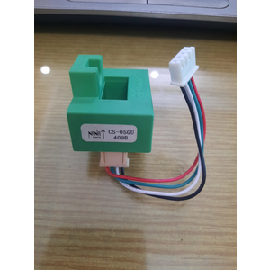
| ITE | Current detection fault |
1. Wires or connectors of control board are loose 2. Hall sensor is damaged. 3. Amplifying circuit is abnormal. |
1. Check the wiring. 2. Ask for support. |
| TE | Autotuning fault | 1. Improper setting of motor rated parameters. 2. Overtime of autotuning. |
1. Set rated parameters according to motor nameplate. 2. Check motor’s wiring. |
| EEP | EEPROM fault | Read/Write fault of control parameters |
Press STOP/RESET to reset Ask for support |
| PIDE | PID feedback fault |
1. PID feedback disconnected. 2. PID feedback source disappears. |
1. Inspect PID feedback signal wire. 2. Inspect PID feedback source. |
| BCE | Brake unit fault | 1. Braking circuit failure or brake tube damaged. 2. Too low resistance of externally connected braking resistor. |
1. Inspect braking unit, replace braking tube. 2. Increase braking resistance. |
| Factory Reserved |