
Kinh Doanh 1: 07.6464.9556 ( Zalo )
Kinh Doanh 2: 0909 752 144
SHIP CODE TOÀN QUỐC*
Kỹ thuật 1: 07 6464 9556 ( Zalo )
Kỹ thuật 2 : 0977 812 351
https://www.tiktok.com/@vinitechdn
Danh mục sản phẩm
Sản phẩm hot


Tin tức

Liên kết website
Thống kê
- Đang online 0
- Hôm nay 0
- Hôm qua 0
- Trong tuần 0
- Trong tháng 0
- Tổng cộng 0
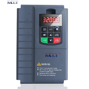
Lỗi biến tần AllenBradley
VINITECH chuyên sửa chữa biến tần, servo tại Đồng Nai, Bình Dương...
Fault Descriptions
| No. | Fault | Type(1) | Description | Action |
| F2 | Auxiliary Input | ➀ | Auxiliary input interlock is open. | 1. Check remote wiring. 2. Verify communications programming for intentional fault. |
| F3 | Power Loss | ➁ | Excessive DC Bus voltage ripple. | 1. Monitor the incoming line for phase loss or line imbalance. 2. Check input line fuse. |
| F4 | UnderVoltage | ➀ | DC bus voltage fell below the minimum value. |
Monitor the incoming AC line for low voltage or line power interruption. |
| F5 | OverVoltage | ➀ | DC bus voltage exceeded maximum value. |
Monitor the AC line for high line voltage or transient conditions. Bus overvoltage can also be caused by motor regeneration. Extend the decel time or install dynamic brake option. |
| F6 | Motor Stalled | ➀ | Drive is unable to accelerate motor. |
Increase P039 - A067 [Accel Time x] or reduce load so drive output current does not exceed the current set by parameter A089 [Current Limit 1]. |
| F7 | Motor Overload | ➀ | Internal electronic overload trip. | 1. An excessive motor load exists. Reduce load so drive output current does not exceed the current set by parameter P033 [Motor OL Current]. 2. Verify A084 [Boost Select] setting |
| F8 | Heatsink OvrTmp |
➀ | Heatsink temperature exceeds a predefined value. |
1. Check for blocked or dirty heat sink fins. Verify that ambient temperature has not exceeded 40°C (104°F) for IP30, NEMA UL Type 1 installations or 50°C (122°F) for IP20/Open type installations. 2. Check fan. |
| F12 | HW OverCurrent | ➁ | The drive output current has exceeded the hardware current limit. |
Check programming. Check for excess load, improper A084 [Boost Select] setting, DC brake volts set too high or other causes of excess current. |
| F13 | Ground Fault | ➁ | A current path to earth ground has been detected at one or more of the drive output terminals. |
Check the motor and external wiring to the drive output terminals for a grounded condition. |
| F29 | Analog Input Loss |
➀ | An analog input is configured to fault on signal loss. A signal loss has occurred. Configure with A122 [Analog In Loss]. |
1. Check parameters. 2. Check for broken/loose connections at inputs. |
| No. | Fault | Type(1) | Description | Action |
| F33 | Auto Rstrt Tries | ➁ | Drive unsuccessfully attempted to reset a fault and resume running for the programmed number of A092 [Auto Rstrt Tries]. |
Correct the cause of the fault and manually clear. |
| F38 | Phase U to Gnd | ➁ | A phase to ground fault has been detected between the drive and motor in this phase. |
1. Check the wiring between the drive and motor. 2. Check motor for grounded phase. 3. Replace drive if fault cannot be cleared. |
| F39 | Phase V to Gnd | |||
| F40 | Phase W to Gnd | |||
| F41 | Phase UV Short | ➁ | Excessive current has been detected between these two output terminals. |
1. Check the motor and drive output terminal wiring for a shorted condition. 2. Replace drive if fault cannot be cleared. |
| F42 | Phase UW Short | |||
| F43 | Phase VW Short | |||
| F48 | Params Defaulted |
The drive was commanded to write default values to EEPROM. |
1. Clear the fault or cycle power to the drive. 2. Program the drive parameters as needed. |
|
| F63 | SW OverCurrent | ➀ | Programmed A098 [SW Current Trip] has been exceeded. |
Check load requirements and A098 [SW Current Trip] setting. |
| F64 | Drive Overload | ➁ | Drive rating of 150% for 1 minute or 200% for 3 seconds has been exceeded. |
Reduce load or extend Accel Time. |
| F70 | Power Unit | ➁ | Failure has been detected in the drive power section. |
1. Cycle power. 2. Replace drive if fault cannot be cleared. |
| F71 | Net Loss | The communication network has faulted. |
1. Cycle power. 2. Check communications cabling. 3. Check network adapter setting. 4. Check external network status. |
|
| F80 | SVC Autotune | The autotune function was either cancelled by the user or failed. |
Restart procedure. | |
| F81 | Comm Loss | ➁ | RS485 (DSI) port stopped communicating. |
1. If adapter was not intentionally disconnected, check wiring to the port. Replace wiring, port expander, adapters or complete drive as required. 2. Check connection. 3. An adapter was intentionally disconnected. 4. Turn off using A105 [Comm Loss Action]. |
| F100 | Parameter Checksum |
➁ | The checksum read from the board does not match the checksum calculated. |
Set P041 [Reset To Defalts] to option 1 “Reset Defaults”. |
| F122 | I/O Board Fail | ➁ | Failure has been detected in the drive control and I/O section. |
1. Cycle power. 2. Replace drive if fault cannot be cleared. |